The definition and purpose of quenching
The steel is heated to a temperature above the critical point Ac3 (hypoeutectoid steel) or Ac1 (hypereutectoid steel), kept for a period of time to make it fully or partially austenitized, and then cooled at a speed greater than the critical quenching speed. The heat treatment process that transforms supercooled austenite into martensite or lower bainite is called quenching.
The purpose of quenching is to transform the supercooled austenite into martensite or bainite to obtain a martensite or lower bainite structure, which is then combined with tempering at different temperatures to greatly improve the strength, hardness, and resistance of the steel. Wearability, fatigue strength and toughness, etc., to meet the different use requirements of various mechanical parts and tools. Quenching can also be used to meet the special physical and chemical properties of certain special steels such as ferromagnetism and corrosion resistance.
When steel parts are cooled in a quenching medium with changes in physical state, the cooling process is generally divided into the following three stages: vapor film stage, boiling stage, and convection stage.
Hardenability of steel
Hardenability and hardenability are two performance indicators that characterize the ability of steel to undergo quenching. They are also important basis for material selection and use.
1. The concepts of hardenability and hardenability
Hardenability is the ability of steel to achieve the highest hardness it can achieve when quenched and hardened under ideal conditions. The main factor that determines the hardenability of steel is the carbon content of the steel. To be more precise, it is the carbon content dissolved in the austenite during quenching and heating. The higher the carbon content, the higher the hardenability of the steel. . The alloying elements in steel have little impact on the hardenability, but they have a significant impact on the hardenability of the steel.
Hardenability refers to the characteristics that determine the hardening depth and hardness distribution of steel under specified conditions. That is, the ability to obtain the depth of the hardened layer when steel is quenched. It is an inherent property of steel. Hardenability actually reflects the ease with which austenite transforms into martensite when the steel is quenched. It is mainly related to the stability of the supercooled austenite of the steel, or to the critical quenching cooling rate of the steel.
It should also be pointed out that the hardenability of steel must be distinguished from the effective hardening depth of steel parts under specific quenching conditions. The hardenability of steel is an inherent property of the steel itself. It only depends on its own internal factors and has nothing to do with external factors. The effective hardenability depth of steel not only depends on the hardenability of the steel, but also depends on the material used. It is related to external factors such as the cooling medium and workpiece size. For example, under the same austenitizing conditions, the hardenability of the same steel is the same, but the effective hardening depth of water quenching is larger than that of oil quenching, and small parts are smaller than oil quenching. The effective hardening depth of large parts is large. This cannot be said to be that water quenching has higher hardenability than oil quenching. It cannot be said that small parts have higher hardenability than large parts. It can be seen that to evaluate the hardenability of steel, the influence of external factors such as workpiece shape, size, cooling medium, etc. must be eliminated.
In addition, since hardenability and hardenability are two different concepts, steel with high hardness after quenching does not necessarily have high hardenability; and steel with low hardness may also have high hardenability.
2. Factors affecting hardenability
The hardenability of steel depends on the stability of austenite. Any factor that can improve the stability of supercooled austenite, shift the C curve to the right, and thereby reduce the critical cooling rate can improve the hardenability of high steel. The stability of austenite mainly depends on its chemical composition, grain size and composition uniformity, which are related to the chemical composition of the steel and heating conditions.
3.Measurement method of hardenability
There are many methods to measure the hardenability of steel, the most commonly used ones are the critical diameter measurement method and the end-hardenability test method.
(1)Critical diameter measurement method
After the steel is quenched in a certain medium, the maximum diameter when the core obtains all martensite or 50% martensite structure is called the critical diameter, represented by Dc. The critical diameter measurement method is to make a series of round rods with different diameters, and after quenching, measure the hardness U curve distributed along the diameter on each sample section, and find the rod with the semi-martensite structure in the center. The diameter of the round rod That is the critical diameter. The larger the critical diameter, the higher the hardenability of the steel.
(2) End quenching test method
The end-quenching test method uses a standard size end-quenched specimen (Ф25mm×100mm). After austenitization, water is sprayed on one end of the specimen on special equipment to cool it. After cooling, the hardness is measured along the axis direction – from the water-cooled end. Test method for distance relationship curve. The end-hardening test method is one of the methods to determine the hardenability of steel. Its advantages are simple operation and wide application range.
4.Quenching stress, deformation and cracking
(1) Internal stress of the workpiece during quenching
When the workpiece is rapidly cooled in the quenching medium, since the workpiece has a certain size and the thermal conductivity coefficient is also a certain value, a certain temperature gradient will occur along the inner section of the workpiece during the cooling process. The surface temperature is low, the core temperature is high, and the surface and core temperatures are high. There is a temperature difference. During the cooling process of the workpiece, there are also two physical phenomena: one is thermal expansion, as the temperature drops, the line length of the workpiece will shrink; the other is the transformation of austenite to martensite when the temperature drops to the martensite transformation point. , which will increase the specific volume. Due to the temperature difference during the cooling process, the amount of thermal expansion will be different at different parts along the cross section of the workpiece, and internal stress will be generated in different parts of the workpiece. Due to the existence of temperature differences within the workpiece, there may also be parts where the temperature drops faster than the point where martensite occurs. Transformation, the volume expands, and the parts with high temperature are still higher than the point and are still in the austenite state. These different parts will also generate internal stress due to differences in specific volume changes. Therefore, two kinds of internal stress may be generated during the quenching and cooling process: one is thermal stress; the other is tissue stress.
According to the existence time characteristics of internal stress, it can also be divided into instantaneous stress and residual stress. The internal stress generated by the workpiece at a certain moment during the cooling process is called instantaneous stress; after the workpiece is cooled, the stress remaining inside the workpiece is called residual stress.
Thermal stress refers to the stress caused by inconsistent thermal expansion (or cold contraction) due to temperature differences in different parts of the workpiece when it is heated (or cooled).
Now take a solid cylinder as an example to illustrate the formation and change rules of internal stress during its cooling process. Only the axial stress is discussed here. At the beginning of cooling, because the surface cools quickly, the temperature is low, and shrinks a lot, while the core is cooled, the temperature is high, and the shrinkage is small. As a result, the surface and the inside are mutually restrained, resulting in tensile stress on the surface, while the core is under pressure. stress. As cooling proceeds, the temperature difference between the inside and outside increases, and the internal stress also increases accordingly. When the stress increases to exceed the yield strength at this temperature, plastic deformation occurs. Since the thickness of the heart is higher than that of the surface, the heart always contracts axially first. As a result of plastic deformation, the internal stress no longer increases. After cooling to a certain period of time, the decrease in surface temperature will gradually slow down, and its shrinkage will also gradually decrease. At this time, the core is still shrinking, so the tensile stress on the surface and the compressive stress on the core will gradually decrease until they disappear. However, as cooling continues, the surface humidity becomes lower and lower, and the amount of shrinkage becomes less and less, or even stops shrinking. Since the temperature in the core is still high, it will continue to shrink, and finally compressive stress will be formed on the surface of the workpiece, while the core will have tensile stress. However, since the temperature is low, plastic deformation is not easy to occur, so this stress will increase as cooling proceeds. It continues to increase and finally remains inside the workpiece as residual stress.
It can be seen that the thermal stress during the cooling process initially causes the surface layer to be stretched and the core to be compressed, and the remaining residual stress is the surface layer to be compressed and the core to be stretched.
To sum up, the thermal stress generated during quenching cooling is caused by the cross-sectional temperature difference during the cooling process. The greater the cooling rate and the greater the cross-sectional temperature difference, the greater the thermal stress generated. Under the same cooling medium conditions, the higher the heating temperature of the workpiece, the larger the size, the smaller the thermal conductivity of the steel, the greater the temperature difference within the workpiece, and the greater the thermal stress. If the workpiece is cooled unevenly at high temperature, it will be distorted and deformed. If the instantaneous tensile stress generated during the cooling process of the workpiece is greater than the tensile strength of the material, quenching cracks will occur.
Phase transformation stress refers to the stress caused by the different timing of phase transformation in various parts of the workpiece during the heat treatment process, also known as tissue stress.
During quenching and rapid cooling, when the surface layer is cooled to the Ms point, martensitic transformation occurs and causes volume expansion. However, due to the obstruction of the core that has not yet undergone transformation, the surface layer generates compressive stress, while the core has tensile stress. When the stress is large enough, it will cause deformation. When the core is cooled to the Ms point, it will also undergo martensitic transformation and expand in volume. However, due to the constraints of the transformed surface layer with low plasticity and high strength, its final residual stress will be in the form of surface tension, and the core will Under pressure. It can be seen that the change and final state of phase transformation stress are exactly opposite to thermal stress. Moreover, since phase change stress occurs at low temperatures with low plasticity, deformation is difficult at this time, so phase change stress is more likely to cause cracking of the workpiece.
There are many factors that affect the size of the phase transformation stress. The faster the cooling rate of the steel in the martensite transformation temperature range, the larger the size of the steel piece, the worse the thermal conductivity of the steel, the larger the specific volume of martensite, the greater the phase transformation stress. The bigger it gets. In addition, the phase transformation stress is also related to the composition of the steel and the hardenability of the steel. For example, high carbon high alloy steel increases the specific volume of martensite due to its high carbon content, which should increase the phase transformation stress of the steel. However, as the carbon content increases, the Ms point decreases, and there is a large amount of retained austenite after quenching. Its volume expansion decreases and the residual stress is low.
(2) Deformation of the workpiece during quenching
During quenching, there are two main types of deformation in the workpiece: one is the change in the geometric shape of the workpiece, which is manifested as changes in size and shape, often called warping deformation, which is caused by quenching stress; the other is volume deformation. , which manifests itself as a proportional expansion or contraction of the volume of the workpiece, which is caused by the change in specific volume during phase change.
Warping deformation also includes shape deformation and twisting deformation. Twist deformation is mainly caused by improper placement of the workpiece in the furnace during heating, or lack of shaping treatment after deformation correction before quenching, or uneven cooling of various parts of the workpiece when the workpiece is cooled. This deformation can be analyzed and solved for specific situations. The following mainly discusses volume deformation and shape deformation.
1) Causes of quenching deformation and its changing rules
Volume deformation caused by structural transformation The structural state of the workpiece before quenching is generally pearlite, that is, a mixed structure of ferrite and cementite, and after quenching it is a martensitic structure. The different specific volumes of these tissues will cause volume changes before and after quenching, resulting in deformation. However, this deformation only causes the workpiece to expand and contract proportionally, so it does not change the shape of the workpiece.
In addition, the more martensite in the structure after heat treatment, or the higher the carbon content in martensite, the greater its volume expansion, and the greater the amount of retained austenite, the less volume expansion. Therefore, the volume change can be controlled by controlling the relative content of martensite and residual martensite during heat treatment. If controlled properly, the volume will neither expand nor shrink.
Shape deformation caused by thermal stress Deformation caused by thermal stress occurs in high temperature areas where the yield strength of steel parts is low, the plasticity is high, the surface cools quickly, and the temperature difference between the inside and outside of the workpiece is the largest. At this time, the instantaneous thermal stress is surface tensile stress and core compressive stress. Since the core temperature is high at this time, the yield strength is much lower than the surface, so it manifests as deformation under the action of multi-directional compressive stress, that is, the cube is spherical in direction. Variety. The result is that the larger one shrinks, while the smaller one expands. For example, a long cylinder shortens in the length direction and expands in the diameter direction.
Shape deformation caused by tissue stress Deformation caused by tissue stress also occurs at the early moment when tissue stress is maximum. At this time, the cross-section temperature difference is large, the core temperature is higher, it is still in the austenite state, the plasticity is good, and the yield strength is low. The instantaneous tissue stress is surface compressive stress and core tensile stress. Therefore, the deformation is manifested as the elongation of the core under the action of multi-directional tensile stress. The result is that under the action of tissue stress, the larger side of the workpiece elongates, while the smaller side shortens. For example, the deformation caused by tissue stress in a long cylinder is elongation in length and reduction in diameter.
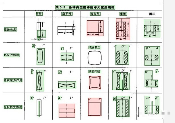
Table 5.3 shows the quenching deformation rules of various typical steel parts.
2) Factors affecting quenching deformation
The factors that affect the quenching deformation are mainly the chemical composition of the steel, the original structure, the geometry of the parts and the heat treatment process.
3) Quenching cracks
Cracks in parts mainly occur in the late stage of quenching and cooling, that is, after the martensitic transformation is basically completed or after complete cooling, brittle failure occurs because the tensile stress in the parts exceeds the fracture strength of the steel. Cracks are usually perpendicular to the direction of maximum tensile deformation, so different forms of cracks in parts mainly depend on the stress distribution state.
Common types of quenching cracks: Longitudinal (axial) cracks are mainly generated when the tangential tensile stress exceeds the breaking strength of the material; transverse cracks are formed when the large axial tensile stress formed on the inner surface of the part exceeds the breaking strength of the material. Cracks; network cracks are formed under the action of two-dimensional tensile stress on the surface; peeling cracks occur in a very thin hardened layer, which may occur when the stress changes sharply and excessive tensile stress acts in the radial direction. Kind of crack.
Longitudinal cracks are also called axial cracks. Cracks occur at the maximum tensile stress near the surface of the part, and have a certain depth towards the center. The direction of the cracks is generally parallel to the axis, but the direction may also change when there is stress concentration in the part or when there are internal structural defects.
After the workpiece is completely quenched, longitudinal cracks are prone to occur. This is related to the large tangential tensile stress on the surface of the quenched workpiece. As the carbon content of the steel increases, the tendency to form longitudinal cracks increases. Low carbon steel has a small specific volume of martensite and strong thermal stress. There is a large residual compressive stress on the surface, so it is not easy to be quenched. As the carbon content increases, the surface compressive stress decreases and the structural stress increases. At the same time, the peak tensile stress moves toward the surface layer. Therefore, high carbon steel is prone to longitudinal quenching cracks when overheated.
The size of the parts directly affects the size and distribution of residual stress, and its quenching cracking tendency is also different. Longitudinal cracks are also easily formed by quenching within the hazardous cross-section size range. In addition, the blockage of steel raw materials often causes longitudinal cracks. Since most steel parts are made by rolling, non-gold inclusions, carbides, etc. in the steel are distributed along the deformation direction, causing the steel to be anisotropic. For example, if the tool steel has a band-like structure, its transverse fracture strength after quenching is 30% to 50% smaller than the longitudinal fracture strength. If there are factors such as non-gold inclusions in the steel that cause stress concentration, even if the tangential stress is greater than the axial stress, Longitudinal cracks are easy to form under low stress conditions. For this reason, strict control of the level of non-metallic inclusions and sugar in steel is an important factor in preventing quenching cracks.
The internal stress distribution characteristics of transverse cracks and arc cracks are: the surface is subject to compressive stress. After leaving the surface for a certain distance, the compressive stress changes to a large tensile stress. The crack occurs in the area of the tensile stress, and then when the internal stress It spreads to the surface of the part only if it is redistributed or the brittleness of the steel further increases.
Transverse cracks often occur in large shaft parts, such as rollers, turbine rotors or other shaft parts. The characteristics of the cracks are that they are perpendicular to the axis direction and break from the inside to the outside. They are often formed before being hardened and are caused by thermal stress. Large forgings often have metallurgical defects such as pores, inclusions, forging cracks and white spots. These defects serve as the starting point of fracture and break under the action of axial tensile stress. Arc cracks are caused by thermal stress and are usually distributed in an arc shape at the parts where the shape of the part changes. It mainly occurs inside the workpiece or near sharp edges, grooves and holes, and is distributed in an arc shape. When high-carbon steel parts with a diameter or thickness of 80 to 100 mm or more are not quenched, the surface will show compressive stress and the center will show tensile stress. Stress, the maximum tensile stress occurs in the transition zone from the hardened layer to the non-hardened layer, and arc cracks occur in these areas. In addition, the cooling rate at sharp edges and corners is fast and all are quenched. When transitioning to gentle parts, that is, to the unhardened area, the maximum tensile stress zone appears here, so arc cracks are prone to occur. The cooling rate near the pin hole, groove or center hole of the workpiece is slow, the corresponding hardened layer is thin, and the tensile stress near the hardened transition zone can easily cause arc cracks.
Reticular cracks, also known as surface cracks, are surface cracks. The depth of the crack is shallow, generally around 0.01~1.5mm. The main characteristic of this kind of crack is that the arbitrary direction of the crack has nothing to do with the shape of the part. Many cracks are connected to each other to form a network and are widely distributed. When the crack depth is larger, such as more than 1 mm, the network characteristics disappear and become randomly oriented or longitudinally distributed cracks. Network cracks are related to the state of two-dimensional tensile stress on the surface.
High carbon or carburized steel parts with a decarburized layer on the surface are prone to form network cracks during quenching. This is because the surface layer has lower carbon content and smaller specific volume than the inner layer of martensite. During quenching, the surface layer of the carbide is subjected to tensile stress. Parts whose dephosphorization layer has not been completely removed during mechanical processing will also form network cracks during high-frequency or flame surface quenching. To avoid such cracks, the surface quality of the parts should be strictly controlled, and oxidation welding should be prevented during heat treatment. In addition, after the forging die is used for a certain period of time, thermal fatigue cracks that appear in strips or networks in the cavity and cracks in the grinding process of quenched parts all belong to this form.
Peeling cracks occur in a very narrow area of the surface layer. Compressive stress acts in the axial and tangential directions, and tensile stress occurs in the radial direction. The cracks are parallel to the surface of the part. The peeling off of the hardened layer after surface quenching and carburizing parts are cooled belongs to Such cracks. Its occurrence is related to the uneven structure in the hardened layer. For example, after alloy carburized steel is cooled at a certain speed, the structure in the carburized layer is: outer layer of extremely fine pearlite + carbide, and the sublayer is martensite + residual Austenite, the inner layer is fine pearlite or extremely fine pearlite structure. Since the formation specific volume of sub-layer martensite is the largest, the result of volume expansion is that compressive stress acts on the surface layer in the axial and tangential directions, and tensile stress occurs in the radial direction, and a stress mutation occurs to the inside, transitioning to a compressive stress state, and peeling cracks Occurs in extremely thin areas where stress transitions sharply. Generally, cracks lurk inside parallel to the surface, and in severe cases may cause surface peeling. If the cooling rate of carburized parts is accelerated or reduced, a uniform martensite structure or ultra-fine pearlite structure can be obtained in the carburized layer, which can prevent the occurrence of such cracks. In addition, during high-frequency or flame surface quenching, the surface is often overheated and the structural inhomogeneity along the hardened layer can easily form such surface cracks.
Microcracks are different from the four aforementioned cracks in that they are caused by microstress. Intergranular cracks that appear after quenching, overheating and grinding of high-carbon tool steel or carburized workpieces, as well as cracks caused by not timely tempering of quenched parts, are all related to the existence and subsequent expansion of microcracks in the steel.
Microcracks must be examined under a microscope. They usually occur at the original austenite grain boundaries or at the junction of martensite sheets. Some cracks penetrate the martensite sheets. Research shows that microcracks are more common in flaky twinned martensite. The reason is that the flaky martensite collides with each other when growing at a high speed and generates high stress. However, the twinned martensite itself is brittle and cannot produce Plastic deformation relaxes stress, thus easily causing microcracks. The austenite grains are coarse and the susceptibility to microcracks increases. The presence of microcracks in the steel will significantly reduce the strength and plasticity of the quenched parts, leading to early damage (fracture) of the parts.
To avoid microcracks in high-carbon steel parts, measures such as lower quenching heating temperature, obtaining fine martensite structure, and reducing the carbon content in martensite can be adopted. In addition, timely tempering after quenching is an effective method to reduce internal stress. Tests have proven that after sufficient tempering above 200°C, the carbides precipitated at the cracks have the effect of “welding” the cracks, which can significantly reduce the hazards of microcracks.
The above is a discussion of the causes and prevention methods of cracks based on the crack distribution pattern. In actual production, the distribution of cracks varies due to factors such as steel quality, part shape, and hot and cold processing technology. Sometimes cracks already exist before heat treatment and further expand during the quenching process; sometimes several forms of cracks may appear in the same part at the same time. In this case, based on the morphological characteristics of the crack, macroscopic analysis of the fracture surface, metallographic examination, and when necessary, chemical analysis and other methods should be used to conduct a comprehensive analysis from the material quality, organizational structure to the causes of heat treatment stress to find the crack. the main causes and then determine effective preventive measures.
Fracture analysis of cracks is an important method to analyze the causes of cracks. Any fracture has a starting point for cracks. Quenching cracks usually start from the convergence point of radial cracks.
If the origin of the crack exists on the surface of the part, it means that the crack is caused by excessive tensile stress on the surface. If there are no structural defects such as inclusions on the surface, but there are stress concentration factors such as severe knife marks, oxide scale, sharp corners of steel parts, or structural mutation parts, cracks can occur.
If the origin of the crack is inside the part, it is related to material defects or excessive internal residual tensile stress. The fracture surface of normal quenching is gray and fine porcelain. If the fracture surface is dark gray and rough, it is caused by overheating or the original tissue is thick.
Generally speaking, there should be no oxidation color on the glass section of the quenching crack, and there should be no decarburization around the crack. If there is decarburization around the crack or an oxidized color on the crack section, it indicates that the part already had cracks before quenching, and the original cracks will expand under the influence of heat treatment stress. If segregated carbides and inclusions are seen near the cracks of the part, it means that the cracks are related to the severe segregation of carbides in the raw material or the presence of inclusions. If cracks only appear at the sharp corners or shape mutation parts of the part without the above phenomenon, it means that the crack is caused by unreasonable structural design of the part or improper measures to prevent cracks, or excessive heat treatment stress.
In addition, cracks in chemical heat treatment and surface quenching parts mostly appear near the hardened layer. Improving the structure of the hardened layer and reducing heat treatment stress are important ways to avoid surface cracks.
Post time: May-22-2024